Turkish
  English
  Russian
  Spanish
  French
  German
  Japanese
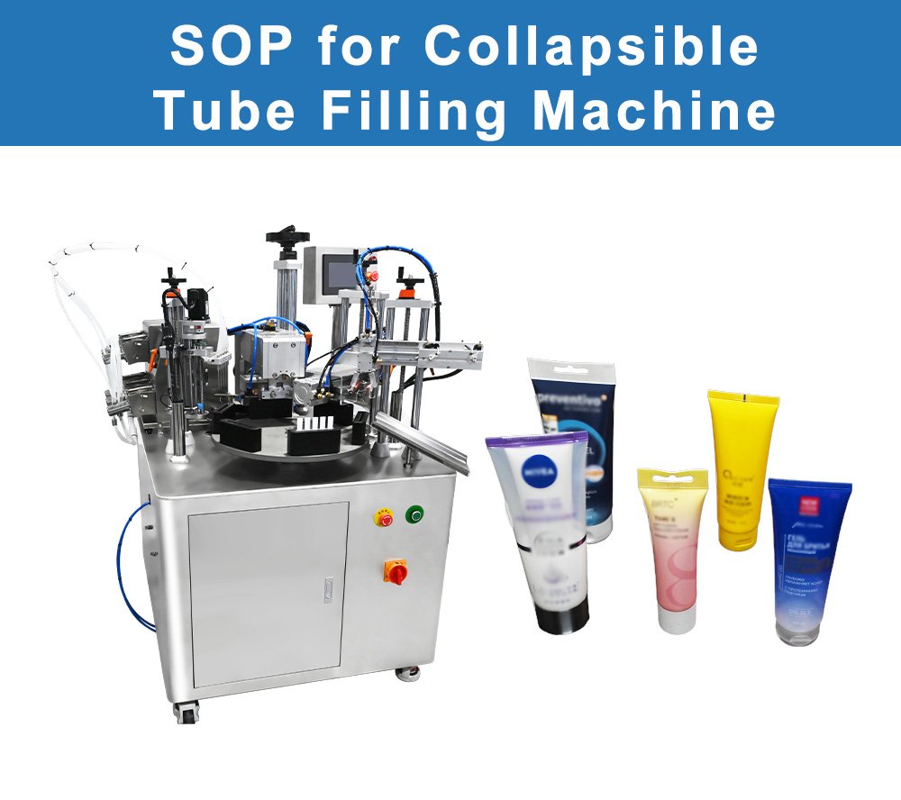
Katlanabilir Tüp Dolum Makinesinin Standart Çalışma Prosedürü.
1.0 AMAÇ:
Kremler, merhemler, jeller ve macunlar gibi yarı katı ilaç formlarının alüminyum, laminat veya plastik tüplere doldurulmasında kullanılan Katlanabilir Tüp Dolum Makinesinin Çalışma Prosedürünü belirlemek.
2.0 KAPSAM:
Bu Prosedür, tesisin yarı katı ürün üretim bölümünde kullanılan Katlanabilir Tüp Dolum Makinesinin Çalışma Prosedürünü kapsamaktadır.
3.0 SORUMLULUK:
Tüp Dolum Operatörü ve Üretim Sorumlusu
4.0 SORUMLULUK:
Üretim Bölümü Şefi.
5.0 İŞLEM:
5.1 Tüp dolum alanını gezin ve makine gövdesini inceleyin. Çalışmaya başlamadan önce, üniteye “TEMİZLENDİ” etiketinin yapıştırılmış olduğunu kontrol edin.
5.2 Ekipman Kullanım Formuna devreye alma bilgilerini girin. Operatör adını, ürün adını, parti numarasını, tarihi ve işe başlama saatini doldurun.
5.3 “TEMİZLENDİ” etiketini çıkarın ve yerine “İŞLEMDE” etiketini takın.
5.4 Üretim Süreci Kalite Güvencesi (IPQA) biriminden Hat Açıklığı onayını alın. Onay belgesi makineye ulaşana kadar üretim beklemelidir.
5.5 Güvenlik Hususları:
5.5.1 Tüp haznesi, kremler ve merhemler için ürünü yüksek bir sıcaklıkta tutar. Ceket, ürün sınıfına bağlı olarak 40 ila 70 °C arasında çalışır. Çalışma sırasında haznenin duvarına çıplak elle dokunmayınız.
5.5.2 Sıkma çeneleri oldukça büyük bir kuvvetle kapanır. Parmaklarınızı her zaman çene bölgesinden uzak tutun. Çeneler yarım saniyeden daha kısa bir sürede sıkıca kapanabilir.
5.5.3 Yönlendirme istasyonunda keskin kenarlar ve yaylı parmaklar bulunmaktadır. Taret dönerken asla yönlendirme yuvasına elinizi sokmayın.
5.5.4 Sıcak hava sızdırmazlık üniteleri, 250 °C veya daha yüksek sıcaklıkta hava üretir. Sıcak hava nozulu, kapatıldıktan sonra birkaç dakika boyunca sıcak kalır. Bu alanı “sıcak yüzey” işareti ile işaretleyin.
5.5.5 Tüp tepsisi ve indeksleme zinciri çevresindeki sıkışma noktalarına dikkat edin. Dökülen saçlar, laboratuvar önlüğünün kolları veya takılar hareketli parçalara takılabilir.
5.5.6 Elektrik panosunu ıslak bir bezle temizlemeyin. Su girişi, kontrol kartında kısa devreye neden olabilir ve yanlış alarmlara yol açabilir.
5.5.7 Tüp tepsisi yükleme noktasının çevresinde takılma tehlikesi sıkça görülür. Yükleyici çevresindeki zemini boş karton kutulardan ve ambalaj atıklarından temiz tutun.
5.5.8 Bu makine için gerekli kişisel koruyucu donanım (KKD) şunlardır: laboratuvar önlüğü, hazne ile çalışırken kullanılacak ısıya dayanıklı eldivenler, koruyucu gözlük, burunlu ayakkabılar ve saç filesi. Ürün havada asılı partiküller oluşturuyorsa, bir toz maskesi de takılmalıdır.
5.5.9 Aşağıdaki güvenlik testlerini haftalık olarak gerçekleştirin ve sonuçları kayda geçirin:
5.5.9.1 Ana kesiciyi kapatın ve HMI ekranının beş saniye içinde karardığını kontrol edin.
5.5.9.2 Acil durdurma düğmesine basın. Döner kafa, çeyrek tur içinde yerine kilitlenmelidir.
5.5.9.3 Her bir güvenlik kapağını tek tek kaldırın. Herhangi bir kapağın açılması, kilitleme mekanizmasını devreye sokmalı ve tahrik sistemini durdurmalıdır.
5.5.9.4 Tepsili yükleyicideki iki kollu bağlanma önleme kontrolünün tasarlandığı gibi çalıştığını doğrulayın.
5.5.9.5 Her kontrol turunun tamamlanmasının ardından Haftalık Güvenlik Kayıt Defteri’ni imzalayın.
5.6 Makine Ayarları:
5.6.1 Tüp Yükleyici ve Tepsi:
5.6.1.1 Boş tüpler, tedarikçiden sunta tepsiler içinde gelir. Her tepside, tüp boyutuna bağlı olarak 144 ile 288 arasında tüp bulunur.
5.6.1.2 Tepsiyi, makinenin arkasındaki yükleme yatağına aktarın. Tepsiyi, boru boyunları toplama koluna bakacak şekilde hizalayın.
5.6.1.3 Alma kolu, tepsiden her seferinde tek bir tüpü kaldırmak için vakum ventuzları kullanır. Yan paneldeki vakum göstergesini kontrol edin. 400 mm Hg’nin altındaki bir değer, emiş gücünün zayıf olduğu anlamına gelir.
5.6.1.4 Tepsideki tüp çapının HMI’daki tarif ayarıyla uyumlu olduğunu kontrol edin. Boyut uyuşmazlığı, aktarım sırasında kolun tüpü düşmesine neden olur.
5.6.1.5 Deforme olmuş veya çökmüş tüpleri, tarete girmeden önce elle ayıklayın. Hasarlı tüpler, yönlendirme istasyonunda sıkışmalara neden olur.
5.6.2 Tüp Yönlendirme ve Göz İşareti Okuyucu:
5.6.2.1 Baskılı tüplerin üzerinde, ön tasarımın hizalamasını belirleyen bir referans işareti bulunur. Makine, mühürleme aşamasından önce her bir tüpü, tasarımın doğru yöne bakacak şekilde hizalamalıdır.
5.6.2.2 Yönlendirme istasyonu, göz işaretini tespit etmek için optik bir sensör kullanır. Sensör merceği temiz olmalı ve ürün kalıntıları içermemelidir.
5.6.2.3 Her partinin başında sensöre göz işareti desenini öğretin. Doğru yönde yerleştirilmiş bir tüpü sensörün altına tutun ve “Öğren” düğmesine basın.
5.6.2.4 Manuel modda beş tüp üzerinde yönlendirme testini gerçekleştirin. Doldurma aşamasına geçilmeden önce her bir tüpte resim ön tarafa bakacak şekilde yerleştirilmelidir.
5.6.2.5 Tüpün hizası bozuk çıkarsa, yönlendirme kabının dönme hızını ayarlayın. Dönme hızı düşük olursa göz işareti ıskalanabilir. Dönme hızı yüksek olursa hedef konumun ötesine geçilebilir.
5.6.3 Ürün Haznesi ve Ceket:
5.6.3.1 Ürün haznesi, 20 ila 50 litre kapasiteli, ceketli bir paslanmaz çelik kaptır. Ceket, yarı katı ürünleri dolum sıcaklığında tutmak için sıcak su dolaştırır.
5.6.3.2 Su ceketi hatlarını sıcaklık kontrol ünitesine bağlayın. Hedef sıcaklığı, kullandığınız partiye ait ürün bültenine göre ayarlayın.
5.6.3.3 Ürünü üst kapaktan hazneye doldurun. Temiz bir paslanmaz kepçe veya ürün aktarım pompası kullanın. Maksimum seviye çizgisini aşacak şekilde aşırı doldurmayın.
5.6.3.4 Hazne karıştırıcısını düşük hızda çalıştırın. Karıştırıcı, topakları parçalar ve işlem süresince ürünün kıvamının sabit kalmasını sağlar.
5.6.3.5 İlk tüp makineye girmeden önce, ürünün dolum sıcaklığına ulaşması için 15 ila 30 dakika bekleyin. Soğuk bir ürün düzgün bir şekilde doldurulamaz.
5.6.4 Dolum Nozulu ve Dozaj Sistemi:
5.6.4.1 Dolum nozulu, açık arka uçtan tüpün içine girer. Nozul, tüpün içine doğru alçalır, yukarı çıkarken dozu verir ve geri emme hareketiyle geri çekilir.
5.6.4.2 Dolum hacmini dozaj ekranından ayarlayın. Bu aralık, makine modeline ve nozul setine bağlı olarak 2 gram ile 150 gram arasında değişmektedir.
5.6.4.3 Geri çekme işlevi, her dolumun sonunda ürünü nozüle doğru çeker. Bu işlem, dış boruda ürün iplikçiklerinin oluşmasını ve ürün damlamalarını önler.
5.6.4.4 Nozul çapını boru açıklığına uygun hale getirin. Çok geniş bir nozul, boru duvarlarını sıyırır. Çok dar bir nozul ise ürünü yüksek hızda etrafa sıçratır.
5.6.4.5 Nozulu, taretteki her bir tüp yuvasının üzerine ortalayın. Yanlış konumlandırılmış bir nozul, doldurma stroku sırasında tüpü bükebilir veya delebilir.
5.7 Sızdırmazlık Yöntemleri:
5.7.1 Alüminyum Boru Sıkma:
5.7.1.1 Alüminyum tüpler, açık uçlarının katlanıp kıvrılmasıyla kapatılır. Bu kıvrım, ürün sızıntısını ve hava girişini önleyen hava geçirmez bir kapak oluşturur.
5.7.1.2 İlk katlama, borunun ucunu düzleştirir. İkinci katlama ise düz kısmı ikiye katlar. Ardından kıvrım çenesi, katlanmış alana bir desen basar.
5.7.1.3 Boru çapına bağlı olarak kıvrım basıncını 40 ile 60 bar arasında ayarlayın. Basıncın çok düşük olması, nakliye sırasında açılabilecek gevşek bir kıvrıma neden olur.
5.7.1.4 Her üretimden önce kıvrım çenelerinin yüzeylerini yumuşak bir fırça ile temizleyin. Çene yüzeyinde kurumuş ürün, kıvrım desenine bulaşır ve gözle görülür lekeler oluşturur.
5.7.1.5 İlk 10 tüpün kıvrım görünümünü kontrol edin. Kıvrımlar paralel olmalı ve çatlak, yarık veya düzensiz kıvrım çizgileri içermemelidir.
5.7.2 Plastik ve Laminat Tüplerin Isıyla Kaynaklanması:
5.7.2.1 Plastik ve laminat tüpler, kıvrılma yerine ısı ile kapatılır. İki çene yumuşayan plastiği birbirine bastırmadan önce sıcak hava açık ucu yumuşatır.
5.7.2.2 Sızdırmazlık istasyonundaki sıcak hava sıcaklığını ayarlayın. Bu aralık, laminat türüne bağlı olarak 250 °C ile 450 °C arasındadır.
5.7.2.3 Sıcak hava bekleme süresini boru duvar kalınlığına göre ayarlayın. İnce duvarlı borular 0,5 saniyede sızdırmaz hale gelir. Kalın duvarlı borular için ise 2 saniyeye kadar süre gerekebilir.
5.7.2.4 Sıcak hava aşamasının hemen ardından sızdırmazlık çeneleri kapanır. Plastik, sızdırmazlık bölgesinden dışarı sızmadan tamamen eriyebilecek şekilde çene basıncını ayarlayın.
5.7.2.5 Her bir tüp üzerindeki sızdırmazlık şeridini inceleyin. Temiz ve düzgün bir şerit, sızdırmazlığın iyi olduğunu gösterir. İnce veya yırtık bir şerit, aşırı ısı veya basınç olduğunu gösterir.
5.8 Kodlama ve Toplu Yazdırma:
5.8.1 Doldurulmuş her tüpte parti kodu ve son kullanma tarihi bulunmalıdır. Bu kod, alüminyum tüplerde kıvrım kısmına, plastik tüplerde ise sızdırmazlık halkasına yazılmalıdır.
5.8.2 Çalıştırma başlamadan önce kodlama tutucusuna doğru tipteki karakterleri yerleştirin. Her bir karakteri parti kaydıyla karşılaştırarak iki kez kontrol edin.
5.8.3 Kodlama adımından sonra ilk beş tüpü çıkarın. 10x büyüteç altında kodu inceleyerek netliğini ve içeriğinin doğruluğunu kontrol edin.
5.8.4 Herhangi bir tüpte kodun silik olması veya eksik olması durumunda üretim hattı durdurulmalıdır. Başka tüpler geçmeden önce sorunun temel nedenini belirleyin.
5.8.5 Çalışma süresince kod kontrol sonucunu her saat başı kayda alın. Kod kalitesinde ani bir düşüş, genellikle karakter kalıplarının aşınmış olmasına veya kodlama tutucusunun hizasız olmasına işaret eder.
5.9 Makine Kontrol Paneli:
5.9.1 Makinenin kontrol panelinde renkli bir HMI, bir acil durdurma düğmesi, bir ana çalıştırma düğmesi ve bir mod seçme anahtarı bulunmaktadır.
5.9.2 Anahtar şalteri kullanarak panelin gücünü açın. HMI, işletim sistemini yaklaşık 45 saniye içinde yükler.
5.9.3 Operatör kimliğinizle oturum açın. Sistem, denetim amacıyla kimliğiniz altında gerçekleştirilen her eylemi kaydeder.
5.9.4 HMI ana ekranında şu çalışma alanları bulunur: Çalıştırma, Ayar, Öğretme, Alarmlar, Raporlar ve Servis.
5.9.4.1 Çalıştırma: Başlat, Durdur, Yavaş Çalıştır ve Beklet düğmelerinin yanı sıra anlık çevrim sayacını içerir.
5.9.4.2 Kurulum: Her bir tüp boyutu ve ürün türü için tarif verilerini saklar.
5.9.4.3 Öğretme: Operatöre, her yeni sanat eseri tasarımı için görüntüleme sistemi eğitimini adım adım yönlendirir.
5.9.4.4 Alarmlar: Mevcut ve geçmiş arızaları, giderme talimatlarıyla birlikte listeler.
5.9.4.5 Raporlar: Vardiya raporlarını, parti özetlerini ve önleyici bakım zamanları listelerini yazdırır.
5.9.4.6 Hizmet: eksen kalibrasyonu ve sensör sıfırlama gibi mühendislik düzeyindeki işlevleri yerine getirir.
5.9.5 Grafiksel makine düzeni, taret üzerindeki her istasyonun anlık konumunu gösterir. Yeşil renk “hazır” anlamına gelir. Sarı renk “işlemde” anlamına gelir. Kırmızı renk “arıza” anlamına gelir.
5.9.6 Döngü hızı göstergesi, dakikadaki tüp sayısını gerçek zamanlı olarak gösterir. Çoğu ürün için hedef hız, dakikada 60 ile 120 tüp arasındadır.
5.9.7 Vardiya sonunda panelden çıkış yapın. Ayarları korumak amacıyla, etkin olmayan oturumlar 10 dakika sonra otomatik olarak kapatılır.
5.10 Toplu İşlemi Çalıştırma:
5.10.1 Çalıştırma ekranında hazne sıcaklığı, karıştırıcı hızı ve ceket akışının hepsinin yeşil renkte olduğunu doğrulayın.
5.10.2 Kurulum alanından ürününüzün üretim tarifesini yükleyin. Her bir parametreyi Toplu Üretim Kaydı (BMR) ile karşılaştırarak kontrol edin.
5.10.3 Doldurma nozulu kaldırılmış ve dozaj sistemi durdurulmuş haldeyken on tüpten oluşan bir kuru döngü çalıştırın. Tüp yükleme, yönlendirme ve sızdırmazlık istasyonlarında herhangi bir sorun olup olmadığını kontrol edin.
5.10.4 Kuru döngü tamamlandıktan sonra doldurma nozülünü indirin ve dozaj sistemini çalıştırın. Nozüldeki hava tamamen boşalana kadar ilk birkaç tüpün içi tam olarak dolmayabilir.
5.10.5 Doldurulmuş ilk on tüpü kalibre edilmiş bir terazi üzerinde tartın. Ortalama ağırlık, hedef dolum ağırlığının ±2% aralığı içinde olmalıdır.
5.10.6 Ağırlık kontrolü başarılı olduğunda partiye devam edin. Üretim süreci kontrolleri için her 30 dakikada bir altı adet numune tüpü alın.
5.10.7 İşlem aşamasındaki her numunenin ağırlığını İşlem Aşaması Kontrol Kayıt Defteri’ne kaydedin. Üst veya alt sınıra doğru sapma gösteren numuneleri işaretleyin.
5.10.8 Denetim penceresinden kıvrım veya sızdırmazlık kalitesini gerçek zamanlı olarak izleyin. Sızdırmazlık görünümündeki bir değişiklik, genellikle tam bir kusurun habercisi olur.
5.10.9 Çalışma sırasında makineden uzaklaşmayın. Kimse gözetimde olmazsa, sıkışmış bir tüp veya besleyici sorunu dakikalar içinde daha ciddi bir duruma dönüşebilir.
5.11 Kusurların Ele Alınması:
5.11.1 Makine, taretin ucunda bir reddetme kolu kullanır. Bu kol, kusurlu tüpleri etiketli bir reddetme oluğuna iter.
5.11.2 Tüp dolum makinesinde sıkça görülen arızalar şunlardır:
5.11.2.1 Ağırlık sınırının altında kalan, yeterince doldurulmamış tüpler.
5.11.2.2 Sızdırmazlık noktasında şişkinlik gösteren aşırı doldurulmuş borular.
5.11.2.3 Kıvrım veya sıcak hava çenelerinin tüp kenarını ıskaladığı durumlarda oluşan çarpık contalar.
5.11.2.4 Mühür bölgesinde eksik veya bulanık parti kodları.
5.11.2.5 Göz işareti okuyucusunun hatalı okumasının ardından resim yönünün yanlış olması.
5.11.3 Vardiya süresince kusurlu tüpleri kusur türüne göre ayırın. Farklı kusur gruplarını tek bir kutuda karıştırmayın.
5.11.4 Sızdırmazlığı iyi olan ancak yeterince doldurulmamış tüpler, arka taraftan yeniden doldurulabilir ve kalite kontrol incelemesinin ardından yeniden kapatılabilir. Bunun için resmi bir düzeltme talebi gereklidir.
5.11.5 Contaları bozuk veya kıvrımları kırılmış tüpler atılmalıdır. Ürünü bir geri kazanım variline boşaltın ve boş tüpleri bertaraf için gönderin.
5.11.6 Vardiya sonunda Hata Kaydı’nı doldurun. Herhangi bir kategoride hata oranının artması durumunda, 24 saat içinde kök neden analizi yapılmalıdır.
5.12 Vardiya Sonu:
5.12.1 Çalışma ekranındaki “Durdur” düğmesine basın. Bir sonraki adıma geçmeden önce, makinenin halihazırda işlenmekte olan tüpleri tamamlamasına izin verin.
5.12.2 Hazne çıkış vanasını kapatın. Bu adım, kapatma işlemi sırasında ürünün doldurma nozülüne akmasını önler.
5.12.3 Haznede kalan ürünü, etiketlenmiş bir geri kazanım kabına boşaltın. Kabı, imha edilmek üzere yarı katı madde depo odasına gönderin.
5.12.4 Hazne ısıtıcısını ve ceket sirkülasyon pompasını kapatın. Hazne, önümüzdeki bir saat içinde ortam sıcaklığına kadar soğuyacaktır.
5.12.5 Çalıştırma ekranındaki Jog kontrolünü kullanarak doldurma nozülünü başlangıç konumuna geri getirin. Aşağı konumda bırakılan bir nozül, gece boyunca tarete damlama yapabilir.
5.12.6 Yükleyiciden kalan boş tüpleri çıkarın ve bunları orijinal tedarikçi tepsisine geri yerleştirin. Tepsiyi, doğru etiketi üzerinde kalacak şekilde tüp depo odasına geri götürün.
5.12.7 Makine bir vardiyadan fazla süreyle çalışmayacaksa, panodan ana gücü kapatın ve ayırıcıyı kilitleyin.
5.12.8 Makineye “TEMİZLENMELİ” etiketini takın.
5.12.9 Katlanabilir Tüp Dolum Makinesini, belirlenen temizlik SOP’sine uygun olarak temizleyin.
5.13 KAYITLAR:
5.13.1 Ekipman Kullanım Formu.
5.13.2 Parti Üretim Kaydı.
5.13.3 İşlemde Olan Kontrol Kaydı.
5.13.4 Haftalık Güvenlik Kaydı.
5.13.5 Hata Kaydı.
5.13.6 Temizlik Kaydı.
6.0 KISALTMALAR:
6.1 Standart İşlem Prosedürü (SOP): Standart İşletme Prosedürü.
6.2 IPQA: Süreç İçi Kalite Güvencesi.
6.3 QA: Kalite Güvencesi.
6.4 Kişisel Koruyucu Ekipman (PPE): Kişisel Koruyucu Ekipman.
6.5 HMI: İnsan Makine Arayüzü.
6.6 BMR: Parti Üretim Kaydı.