French
  English
  Russian
  Turkish
  Spanish
  German
  Japanese
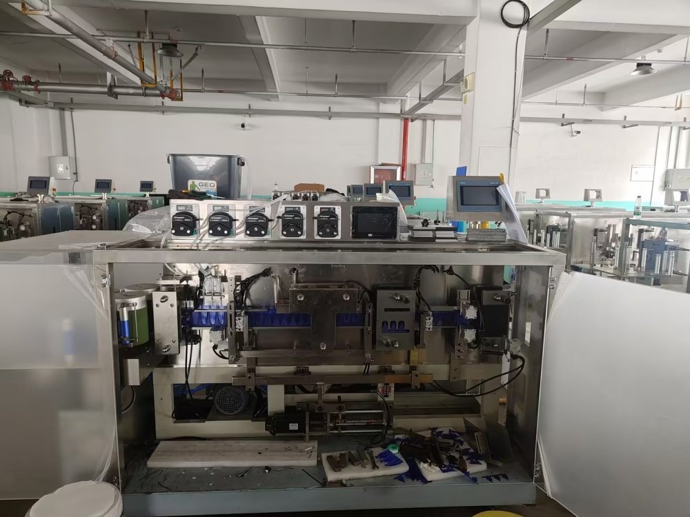
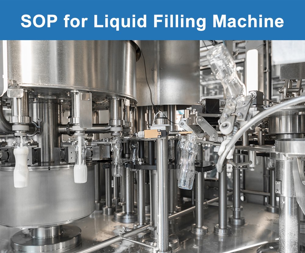
Standard operating procedure of Liquid Filling Machine.
1.0 OBJECTIF :
To describe the Operating Procedure of Liquid Filling Machine used for precise volumetric filling of liquid products of varied viscosity into primary containers.
2.0 CHAMP D'APPLICATION :
This Procedure applies to the Operating Procedure of Liquid Filling Machine installed in the liquid section of the production department.
3.0 RESPONSABILITÉ :
Filling Operator & Production Technologist
4.0 RESPONSABILITÉ :
Production Head.
5.0 PROCÉDURE :
5.1 Walk through the filling area and inspect the machine frame. Make sure the “CLEANED” status tag is fixed to the unit before any work starts.
5.2 Fill out the Equipment Usage Register. Log your name, the product code, the date, and the exact time the shift began.
5.3 Peel off the “CLEANED” status tag and mount the “UNDER PROCESS” status tag in its place.
5.4 Request a Line Clearance from In Process Quality Assurance (IPQA). Do not proceed until a signed and dated clearance reaches you.
5.5 Safety Requirements:
5.5.1 Many liquid products contain alcohols, essential oils, or volatile solvents. Keep all ignition sources such as lighters, mobile phones, and sparking tools away from the filling area.
5.5.2 Slippery floors are a major hazard around liquid fillers. Wipe up any spill the moment it happens and use the yellow wet floor sign until the area dries.
5.5.3 Do not pressurize the product tank above the rated limit shown on the tank nameplate. Over pressure can rupture a fitting and spray product at high force.
5.5.4 Keep the CIP return lines clear at all times. A blocked return line can build up pressure during the clean cycle and damage the tank.
5.5.5 Never reach into the fill heads while the pistons or pumps are moving. The drive force on each piston can pinch or crush a finger without warning.
5.5.6 Wear chemical resistant gloves and a splash apron when you handle product concentrates or cleaning agents. Flush any skin contact under running water for at least 15 minutes and report to the first aid station.
5.5.7 Lift heavy product drums with a trolley or a second person. A full 200 liter drum can weigh over 200 kg and cause a back injury if handled alone.
5.5.8 Standard PPE for this machine includes a lab coat, nitrile gloves, safety glasses, closed shoes, and a hair net. Add a face shield when you work with hot or caustic products.
5.5.9 Complete the safety circuit audit below every week and document it:
5.5.9.1 Isolate the machine with the main disconnect and confirm that all live lights turn off.
5.5.9.2 Strike the emergency stop mushroom. The pumps, drive, and conveyor must all halt in one motion.
5.5.9.3 Open each guard door in turn. The machine should drop into a safe hold state each time.
5.5.9.4 Test the low level probe in the product tank by drawing off some liquid. The line must pause when the probe goes dry.
5.5.9.5 Sign the Safety Audit Log after each weekly review.
5.6 Filling Technology Selection:
5.6.1 Piston Volumetric Filling:
5.6.1.1 The piston filler draws a fixed volume on each stroke. This method suits thin liquids and medium viscosity products up to 5000 cPs.
5.6.1.2 Set the stroke length on the adjuster dial. One full turn usually changes the dose by 1 mL, so move the dial in small steps.
5.6.1.3 Piston fillers give very repeatable doses with less than 0.5% variation between bottles. Select this mode for oral suspensions, syrups, and cough mixtures.
5.6.2 Peristaltic Pump Filling:
5.6.2.1 The peristaltic pump uses rollers to squeeze a silicone tube. The product only touches the tube, not the pump itself.
5.6.2.2 Select this mode for sterile products, small batch runs, or any product that must not contact metal parts.
5.6.2.3 Replace the silicone tube at the intervals listed on the preventive maintenance chart. A stretched tube gives inaccurate fills.
5.6.3 Gravity and Pressure-Time Filling:
5.6.3.1 Gravity fillers rely on head pressure from a tank mounted above the fill heads. This approach suits thin water like liquids that foam easily.
5.6.3.2 The fill volume is controlled by a timed valve rather than a metered stroke. The valve opens for a set duration to release the dose.
5.6.3.3 Keep the tank level constant during the run. A falling level drops the head pressure and shrinks the fill volume bottle by bottle.
5.6.4 Flow Meter Filling:
5.6.4.1 The flow meter filler uses a mass or magnetic flow sensor on each fill line. The sensor counts the exact volume that passes through the nozzle.
5.6.4.2 This mode gives the highest accuracy and adjusts automatically when product density changes. Select this mode for high value products or regulated fills.
5.6.4.3 Calibrate each flow sensor at the start of every batch. A two point calibration at 10% and 90% of full scale is sufficient for most products.
5.7 Product Tank and Feed System:
5.7.1 The product tank is a jacketed stainless steel vessel mounted on load cells. The load cells give a live weight reading of the product on hand.
5.7.2 Connect the product supply line to the inlet port on top of the tank. Tighten the tri clamp by hand first, then finish with a wrench to the torque on the label.
5.7.3 Set the tank jacket temperature as required by your product. Hot syrups need the jacket at 40 to 50°C to keep the viscosity low during the fill.
5.7.4 Start the tank agitator at low speed. Gradually raise the speed to the value listed on the batch record. A quick ramp up can splash product onto the tank lid.
5.7.5 Confirm that the low level and high level probes are active. The machine will pause the fill if either probe loses contact with product.
5.7.6 Check the product transfer pump for leaks at the seal. A wet seal housing points to a worn mechanical seal that needs replacement.
5.7.7 Bleed all air from the feed lines before the first fill. Air pockets in the line cause short fills and bubble formation in the finished product.
5.8 Nozzle and Drip Control:
5.8.1 The fill nozzles are the final stage before product enters the container. Each nozzle must be matched to the product viscosity and the container mouth size.
5.8.2 Fit the diving nozzle head for foamy products. The nozzle dives below the liquid surface during the fill so the product pours without splash or foam.
5.8.3 Set the dive speed to match the fill rate. A slow dive causes overflow. A fast dive creates bubbles at the product surface.
5.8.4 Confirm that the anti drip valve closes fully at the end of each cycle. A leaky valve drips product between fills and contaminates the outer bottle.
5.8.5 Inspect each nozzle tip for product buildup at the start of each shift. Dried residue can block the flow path and cause a short fill.
5.8.6 Swap nozzle sets whenever you change container size. Using a small nozzle on a wide mouth bottle leads to splash marks on the inside wall.
5.9 Product Changeover:
5.9.1 A product changeover requires a full clean of all contact parts. Skipping any step risks cross contamination between products.
5.9.2 Drain all remaining product from the tank through the bottom outlet. Collect any recoverable product in a labeled container for QA review.
5.9.3 Rinse the tank, the feed lines, and the nozzles with purified water for three minutes. The rinse water must run clear at the drain point.
5.9.4 Engage the CIP cycle from the main control panel. The cycle will run hot caustic wash, rinse, acid wash, rinse, and final water for injection rinse.
5.9.5 Verify the conductivity reading of the final rinse water. A reading below 1.3 microsiemens per cm confirms adequate removal of cleaning agents.
5.9.6 Swab test a sample of three contact surfaces after the CIP cycle. Send the swabs to microbiology for bioburden testing.
5.9.7 Replace the nozzle set, tubing, and gaskets if required by the changeover matrix. Some products need new contact parts even after a full clean.
5.9.8 Do not load the new product until QA releases the machine for use. The release comes after satisfactory results from the swab test and the rinse conductivity check.
5.10 HMI Navigation:
5.10.1 The Human Machine Interface uses a 15 inch color touchscreen mounted at operator level. The screen links to the PLC via a fiber optic cable for fast data transfer.
5.10.2 Power up the interface with the secondary enable button after the main panel comes on. The boot sequence takes about 60 seconds.
5.10.3 Log in with your unique user ID and password. The system assigns access rights based on your role: Operator, Technologist, Supervisor, or Engineer.
5.10.4 The home screen displays five tiles: Batch Setup, Fill Control, CIP/SIP, Data Trend, and Audit Trail. Tap any tile to enter that section.
5.10.4.1 Batch Setup: holds the product code, batch number, target volume, and line speed for the current run.
5.10.4.2 Fill Control: shows the live fill status of each head along with the pause, resume, and abort controls.
5.10.4.3 CIP/SIP: runs and monitors the automated clean and steam cycles between batches.
5.10.4.4 Data Trend: plots fill volume, temperature, and tank level over the last 24 hours.
5.10.4.5 Audit Trail: shows a tamper proof log of all operator actions, parameter changes, and fault events.
5.10.5 The alarm bar at the top of the screen turns amber for warnings and red for critical faults. Address red alarms before the run continues.
5.10.6 Log off the HMI at the end of your shift. The screen will lock within 60 seconds if no activity is detected.
5.11 Production Run:
5.11.1 Confirm the tank level, jacket temperature, and agitator speed all read green on the Batch Setup screen.
5.11.2 Run five test fills in Manual mode into labeled beakers. Weigh each beaker on a calibrated balance and compare to the target.
5.11.3 Adjust the fill parameter on the HMI if the average weight falls outside the ±1% tolerance. Re test until all five samples land within tolerance.
5.11.4 Switch the machine to Auto mode once the test fills pass. Tap Start on the Fill Control screen to begin the run.
5.11.5 Watch the first 30 filled containers at the outfeed. Inspect each one for fill level, bubble formation, and nozzle drip marks.
5.11.6 Pull an in process sample of five containers every 30 minutes. Weigh each sample and log the result in the Batch Production Record.
5.11.7 Monitor the Data Trend screen for any drift in fill volume. A steady decline suggests a filter is clogging or a pump seal is wearing.
5.11.8 Report any out of spec sample to the shift supervisor at once. Do not adjust fill parameters mid run without supervisor approval.
5.12 Rejects and Recovery:
5.12.1 The machine has two reject stations along the outfeed conveyor. Each station pushes off containers that fail a specific check.
5.12.2 The first station uses a check weigher. Any container that falls outside the upper or lower weight limit drops onto the reject tray.
5.12.3 The second station uses a fill level camera. The camera rejects containers with air bubbles, foam heads, or low meniscus.
5.12.4 Sort the rejected containers within one hour of production:
5.12.4.1 Low fill containers can be topped up by hand and returned to the line after reinspection.
5.12.4.2 Over fill containers must be emptied back into the recovery tank for blending into the next sub batch.
5.12.4.3 Visually defective containers are set aside for QA disposition.
5.12.5 Record the reject count by category in the Reject Log at shift end. A rising reject trend needs investigation within 24 hours.
5.13 Shut Down Steps:
5.13.1 Press Stop on the Fill Control screen. Let all containers on the conveyor clear the line before the next step.
5.13.2 Drain the remaining product from the tank into a labeled recovery drum. Cover the drum and send it to the quarantine area.
5.13.3 Turn the jacket heater off and let the tank cool to room temperature.
5.13.4 Flush all product lines with purified water for two minutes to clear residual product.
5.13.5 Drop the machine into Safe Hold mode from the HMI. This mode depressurizes the system and parks all pistons at home position.
5.13.6 Switch off the main power at the disconnect and lock it out if the machine will remain idle overnight.
5.13.7 Attach the “ À NETTOYER ” tag on the machine.
5.13.8 Clean the Liquid Filling Machine as per the defined cleaning SOP.
5.14 DOSSIERS :
5.14.1 Equipment Usage Register.
5.14.2 Batch Production Record.
5.14.3 Safety Audit Log.
5.14.4 Reject Log.
5.14.5 CIP Cycle Record.
5.14.6 Cleaning Record.
6.0 ABRÉVIATIONS :
6.1 SOP : Procédure opérationnelle standard.
6.2 IPQA : Assurance qualité en cours de processus.
6.3 AQ : Assurance qualité.
6.4 EPI : Équipement de protection individuelle.
6.5 CIP: Clean In Place.
6.6 SIP: Steam In Place.
6.7 HMI: Interface homme-machine.
6.8 PLC: Programmable Logic Controller.
6.9 cPs: Centipoise.